Ningbo Bohua Mechanical Parts Co., Ltd. · Linda, Export Sales · linda@ningbobohua.com · www.bohua-casting.com
Engineering resource
Pump Housing RFQ Guide: Features, Interfaces, and Inspection
A pump housing RFQ needs a feature map that connects each functional surface to its mating part, manufacturing state, and acceptance requirement. This guide explains the engineering decisions behind pressure boundaries, volutes, bores, ports, and vacuum interfaces. Use it to prepare controlled inputs before comparing casting, machining, and inspection scope.
On this page
- Which Parts of a Pump Housing Need Engineering Inputs?
- How Should the Pressure Boundary Be Defined?
- What Must Be Fixed for the Volute and Cutwater?
- Who Defines Wear-Ring Fit and Running Clearance?
- How Are Seal Chambers and Bearing Bores Checked?
- What Is Needed for Nozzle Loads and Supports?
- How Should Auxiliary Ports and Clocking Be Specified?
- How Do Core Shift, Wall Thickness, and Machining Stock Differ?
- What Changes for Vacuum Pump Housings?
- What Must an Oil-Tank Interface Schedule Include?
- What Is Different About A356-T6 and Fire-Pump Requirements?
- How Should Common Problems Be Investigated?
- Which Records Make the Engineering Decisions Reviewable?
Which Parts of a Pump Housing Need Engineering Inputs?
Map the pressure boundary, flow passages, rotating interfaces, and service connections before choosing the manufacturing and inspection scope.
A pump housing drawing can describe a casting blank or a finished component. Mark which surfaces remain as cast, which are formed by cores, and which receive final machining. Identify the governing file when the drawing, model, and reference sample disagree. A photograph helps explain the shape; it cannot establish the requirements for another design.
| Feature group | Question to resolve | Controlled input |
|---|---|---|
| Pressure boundary | Which cavities must remain isolated? | Section views, fluid boundary, and test configuration |
| Volute and cutwater | Which passage geometry must tooling reproduce? | Approved hydraulic model and impeller relationship |
| Wear-ring, seal, and bearing features | Which mating parts establish fit and alignment? | Mating geometry, datums, and final measurement state |
| Nozzles and supports | Where do piping loads enter and react? | Connection coordinates, load cases, and support condition |
| Auxiliary and vacuum interfaces | What does each opening do after assembly? | Port schedule, closures, seals, and cleaning requirements |
For supplier capability, see pump housing manufacturing. Use this guide to resolve feature questions, then put the agreed requirements into the pump casing pressure-tight RFQ.
At Bohua
The product photographs show aluminum parts Bohua has made. They provide shape references, not material, pressure-rating, or performance evidence for a new drawing.

How Should the Pressure Boundary Be Defined?
Define each isolated cavity and its closures in the state that will actually be tested.
Distinguish leakage to the outside from leakage between internal cavities. Ports, plugs, covers, and machined sealing lands can change the tested boundary. An early casting test may not represent the finished housing because later machining can expose subsurface porosity.
- Mark each test volume and any adjacent cavity that must remain isolated.
- Show temporary closures and their contact areas; a fixture must not conceal a surface being accepted.
- State whether separate cavities require separate test configurations.
- Give pressure units and the gauge or absolute reference. Distinguish operating, proof, and inspection conditions.
- Define the duration, acceptance criterion, test stage, sampling, and required record in the project specification.
- State whether approved rework requires another test and who authorizes release.
At Bohua
Bohua's pressure-tightness test method is air-under-water immersion at 3 bar or more. Impregnation is performed by a qualified subcontractor only with customer approval.
The stated immersion capability is not a housing design pressure or evidence of complete-system vacuum performance. See the pressure-tight casting and testing scope for the component test boundary.
What Must Be Fixed for the Volute and Cutwater?
The pump designer must release the hydraulic geometry before the foundry defines tooling and inspection controls.
The volute collects flow leaving the impeller. The cutwater, or tongue, is the local feature near the impeller and discharge transition. Their relationship affects hydraulic behavior, so a similar-looking casing is not an acceptable geometry master.
| Location | Provide | Agree during review |
|---|---|---|
| Volute passage | Cross-section progression, rotation, and approved flow-path model | Core location references and inspection access |
| Cutwater and throat | Tip geometry, local radii, throat section, and discharge transition | Permitted casting variation and evidence at critical sections |
| Impeller relationship | Impeller diameter reference, axial position, and approved clearance definition | Which mating dimensions the buyer supplies |
| Internal surfaces | As-cast, cored, trimmed, blended, or machined state | Allowed material removal, approval owner, and records |
Keep the pump curve and hydraulic validation with the pump designer. Agree how tooling maintenance or a core change will be checked against the released geometry. Use tilt-pour gravity casting to review the manufacturing route.
Engineering context: Hydraulic Institute, Important Considerations in the Design of Water Pumps, May 15, 2023. This is design context, not a project acceptance standard.
Who Defines Wear-Ring Fit and Running Clearance?
The buyer controls assembled running clearance; the housing drawing controls the supplied bore, seat, or integral running surface.
- Identify an integral stationary running surface, a seat for a separate wear ring, or a design with no wear-ring feature.
- Supply the mating stationary and rotating diameters and their approved revisions.
- Specify whether clearance is radial or diametric and which assembly and temperature condition applies.
- Define seat depth, shoulders, corner geometry, fit, and retention where a separate ring is used.
- Assign ring supply, installation, and final measurement to named parties.
A bore can meet its own diameter requirement while the assembled clearance is wrong. The inspection plan must identify whether acceptance applies before ring installation, after installation, after coating, or to a matched assembly. No universal clearance is implied by the housing name.
How Are Seal Chambers and Bearing Bores Checked?
Measure functional alignment from the drawing datum frame in the required final state.
Separate bearing seats, seal bores, shaft references, and locating pilots. Give each its mating function, size, geometric control, and surface requirement. Preserve the drawing's exact position, runout, or other callout; these controls are not interchangeable.
- Identify the feature that establishes the functional axis.
- Show which surfaces share a machining setup and where a fixture transfer occurs.
- State bearing fit and seal type when they affect the interface review.
- Define whether results are required after heat treatment, final machining, coating, or assembly.
- Request a characteristic list and datum setup with the CMM report; a production gauge needs an agreed correlation plan where applicable.
At Bohua
Dimensional inspection equipment includes Hexagon Global S and NANO Metrology CMM systems. Feasibility for a particular characteristic depends on access, fixturing, and the agreed measurement plan.
A passed leak test does not establish bore alignment. Review the casting and CNC machining scope when allocating machining fixtures and final measurement responsibility.

What Is Needed for Nozzle Loads and Supports?
Provide buyer-approved suction and discharge load cases with the support condition used to evaluate them.
Piping forces and moments can deform a casing and affect alignment. The permissible loads depend on the pump configuration and service conditions. The housing supplier needs controlled component requirements, not a load table copied from another pump.
- Define the coordinate origin, axis directions, sign convention, and application point.
- Identify the force and moment combinations and the operating or test condition for each case.
- Mark feet, lugs, pads, mounting faces, and hardware that react the loads.
- Provide the baseplate interface, contact condition, and support state during measurement.
- Assign allowable-load approval, piping design, and complete-pump validation to the pump or system designer.
Engineering context: KSB, Pump nozzle load. No allowable load values are adopted here.
How Should Auxiliary Ports and Clocking Be Specified?
Give every auxiliary boss a function and a delivered state before assigning its machining operations.
| Field | What to define |
|---|---|
| Function | Drain, vent, gauge, priming, lubrication, test connection, or reserved pad |
| Delivered state | Cast-only, cored, drilled, tapped, plugged, or completed by another assembler |
| Location and clocking | Centerline, angle, or coordinates from named datums and installed orientation |
| Connection | Thread or connector specification and edition, usable depth, spotface, and seal |
| Ownership | Plug selection, supply, installation, temporary test closure, and shipment condition |
A passed thread gauge does not establish port position, sealing-land finish, or remaining wall. Inspect these characteristics separately where the drawing requires them. A reserved boss must remain undrilled unless the released design says otherwise.
How Do Core Shift, Wall Thickness, and Machining Stock Differ?
Check core location, remaining wall, and machining stock as separate characteristics at named sections.
| Characteristic | Question | Required input |
|---|---|---|
| Core location | Is the internal passage correctly positioned? | Passage geometry relative to casting or machining datums |
| Remaining wall | How much material remains beside the passage? | Drawing-defined wall requirement in the accepted state |
| Machining stock | Can the finished surface be produced without breakout or incomplete cleanup? | Finished machining envelope and stock allowance |
Map sections where a cored passage approaches a bore, groove, bolt feature, or sealing face. Choose an inspection method for the actual question and access. A CMM cannot directly measure an inaccessible internal wall. Radiography, accessible measurements, or an approved section study may require different evidence and acceptance rules.
Separate development studies from first-article and production checks. Define what must be repeated after a core-box repair, datum change, or machining-program change. A passed leak test does not approve an undersized wall; only the authorized design owner can accept a dimensional deviation.
At Bohua
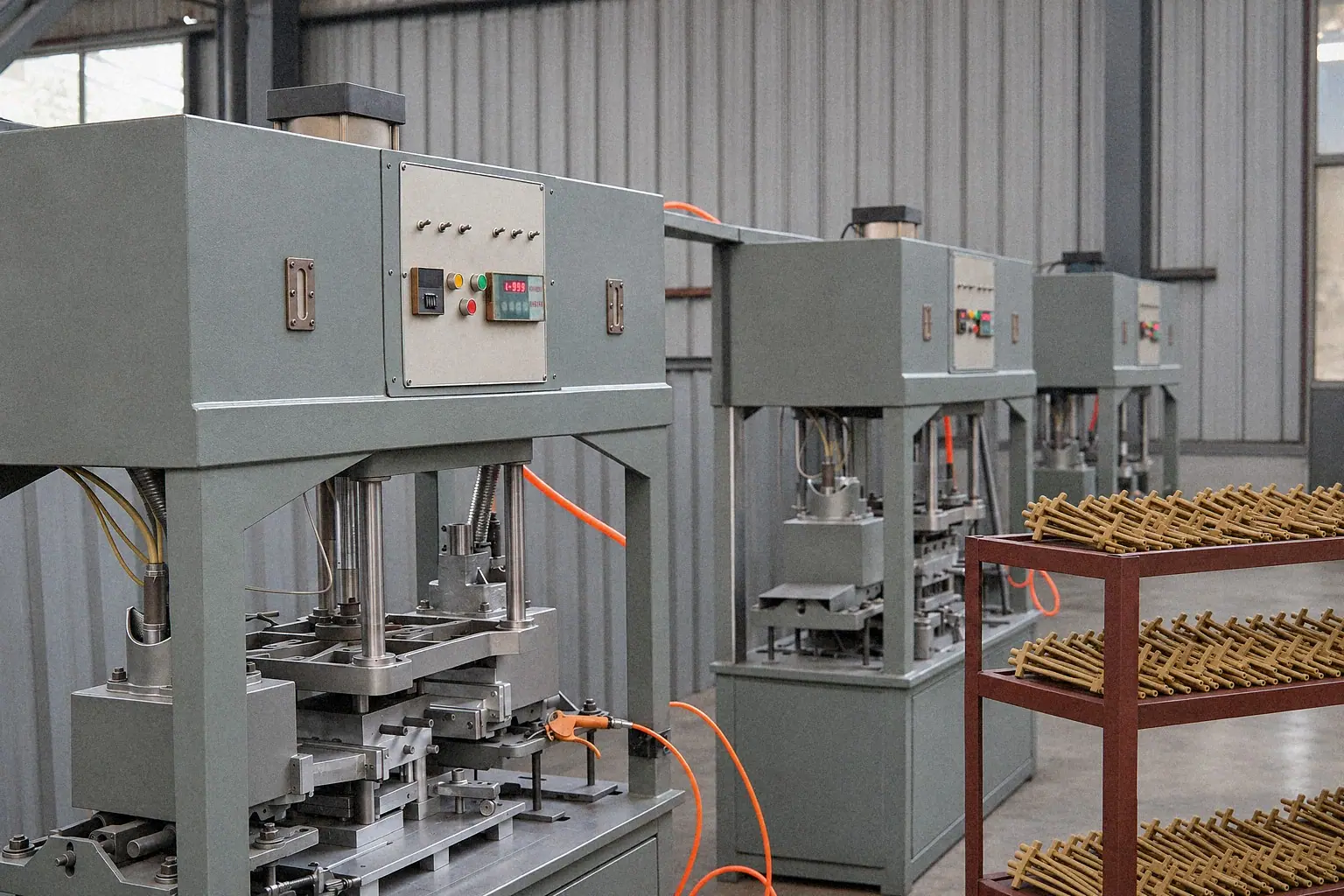
Bohua has 10 hot-box core shooters. Some tilt-pour castings use sand cores.
What Changes for Vacuum Pump Housings?
Define the assembled vacuum boundary and each mating interface without treating component inspection as complete-pump vacuum acceptance.
Blind holes and trapped gas
A real leak connects an external volume to the evacuated system. A trapped volume can instead release enclosed gas slowly through a restricted path. Check blind holes in the assembled state, with the fastener and mating component included.
- Mark only holes and pockets connected to the evacuated volume.
- Define drilled depth, usable thread depth, fastener engagement, bottom clearance, and remaining wall.
- Keep any vent path, through-hole conversion, or special fastener under buyer design approval.
- Specify chip removal, permitted cleaning media, drying, and protection before assembly.
Do not apply a specialized vacuum-hardware rule to every industrial pump. The design owner must validate the chosen mitigation and acceptance method.
Functional bores and cavities
List the pumping cavity, bearing registers, seal bores, pilots, and end faces by function. Include mating references and any required relationship between paired cavities. State whether dimensions apply before or after coating. Rotor, vane, and running-clearance design remain with the pump designer.
O-ring grooves and mating faces
Provide the approved seal design source and revision. Define groove type, width, depth, corners, edge condition, surface texture, machining lay, and datum relationship to the mating face. List unacceptable scratches, pits, and burrs separately from roughness. Protect the groove through cleaning and packing. Dimensional acceptance does not establish assembled vacuum performance.
Inlet and exhaust connections
Identify each connection by function, flange or coupling family, nominal size, controlling specification and edition, seal, and mating hardware. Relate the face, bore, and hole pattern to the housing datums. Assign piping loads, supports, and final-system acceptance to the system designer. A photograph cannot identify the required flange family.
What Must an Oil-Tank Interface Schedule Include?
Locate fill, drain, sight-glass, vent, and cover interfaces from the installed orientation and buyer-controlled oil-level datum.
- Relate the sight-glass window, drain low point, cover, and mounting interfaces to the approved datum.
- Define service access and the final machined and sealed state of each opening.
- Provide the approved sight-glass interface, seal, installation direction, and replacement access.
- Assign supply and installation of plugs, glass, gaskets, covers, and fasteners.
The pump designer sets the operating oil level. Tank-side dimensional inspection, installed sight-glass sealing, and oil-level readability are separate checks. Specify cleaning and protective closures for the empty component if another party performs assembly.
What Is Different About A356-T6 and Fire-Pump Requirements?
Use the approved material specification and assembly obligations; neither an alloy name nor a pump category defines acceptance.
- For A356-T6, state the material specification and edition, temper, and required material and heat-treatment records.
- Identify distortion-sensitive faces and bores, and the machining and measurement stages that control them.
- Provide fluid compatibility and service conditions for engineering review.
- For a fire-pump housing, identify the applicable assembly specification and edition and assign each obligation to its responsible party.
A housing quotation must distinguish component conformity from complete fire-pump performance and approval. No complete-pump certification is established by a casting photograph.
At Bohua
A356 and ZL114 are confirmed materials for gravity and tilt-pour casting. T5 and T6 heat treatment are performed in-house. These capabilities do not establish the specification of an individual photographed part.
See A356 material and delivery-condition inputs and gravity and permanent mold casting capability for the related manufacturing review.
How Should Common Problems Be Investigated?
Record the failure location and process stage before assigning a cause.
| Observed problem | Possible explanation to investigate | Evidence to provide |
|---|---|---|
| Leak after machining | Exposed porosity, a passage breakout, or a closure leak | Marked location, machining stage, and test configuration |
| Cover-interface leakage | Face distortion, surface damage, or inconsistent gasket compression | Local and full-face measurements, gasket stack, and clamping condition |
| Assembly rub or misalignment | Datum transfer, mating-size mismatch, or a changed installed condition | Final bore relationships and mating dimensions |
| Unexpectedly thin wall | Core displacement or an incompatible machining envelope | Critical-section map and remaining-wall results |
| Slow vacuum recovery | External leakage, trapped gas, or retained process media | Assembled boundary, hole map, cleaning history, and test record |
These are investigation paths, not diagnoses. For a replacement-source RFQ, supply available failed-sample photographs and test or section records. Identify missing evidence explicitly. Keep design changes and repair decisions under the agreed approval authority.
Which Records Make the Engineering Decisions Reviewable?
Link each critical feature to a requirement, measurement state, method, result, and approval owner.
- Use the controlled drawing revision and feature reference consistently.
- Identify the tolerance source, datum setup, inspection stage, and fixture.
- Separate first-article results from the production sampling plan.
- Define report format, traceability, retention, and deviation or reinspection authority.
The quality-control capability page helps select relevant equipment. Use the pump casing RFQ page for the commercial package and submission steps. Other preparation guides are available in buyer resources.
Prepare a pump housing RFQ
Use the pump casing RFQ page to define the delivery scope and follow its drawing submission steps. Not sure which process fits? Tell us what the part must do. In a free drawing review, our engineers recommend a process and suggest design changes where needed.
Send your drawing →