
Make vacuum-pump housing quotations comparable by defining each inlet and exhaust connection, flange family, seal, orientation, CNC datum, pipeline-load owner, protection, evidence and test boundary.
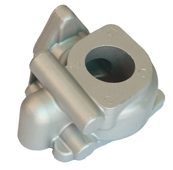
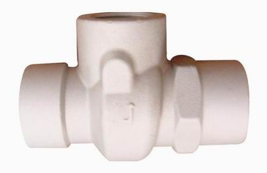
A quote-ready vacuum-pump inlet and exhaust flange RFQ must identify the supplied housing and installed orientation; define every inlet, exhaust, foreline or process connection by function, flange family, nominal size, controlled standard or drawing edition, seal and mating part; relate the final machined face, bore, holes and groove to drawing datums; and assign pipeline-load design, cleanliness, protection, dimensional evidence, and component-versus-system test ownership. A casting supplier should not infer a flange type, allowable load or vacuum acceptance from a photograph or a generic port diameter.
The inlet connects the pump or housing to the process or upstream vacuum path. The exhaust connects it to the downstream exhaust path. Their manufacturing interfaces can include a face, bore, collar, bolt or clamp features, seal carrier, locating geometry and adjacent mounting features. The complete connection also includes buyer-selected mating hardware, piping, supports, seals and assembly conditions. The housing drawing must therefore control what Bohua is asked to cast, machine, inspect, protect and deliver, while the pump or system designer retains the operating and installation decisions not released to the supplier.
Bohua's current site verifies A356-T6 gravity-cast vacuum-system and flow-control housing examples, follow-up machining on sealing faces, ports or mounting points, a casting-plus-CNC route, and project-defined dimensional and pressure-tightness evidence. These pages and approved images establish product-category and workflow relevance only. They do not prove that the pictured parts use a particular vacuum flange family, carry a specified piping load, include buyer hardware, or have passed a new assembly or complete-system vacuum test.
Freeze the supplied component and installed connection map
Start with the pump or system family, housing part number, controlled PDF and STEP revisions, installed coordinate system, flow direction and supply boundary. Number every inlet, exhaust, foreline, purge or temporary test connection and state whether Bohua is quoting a raw casting, heat-treated blank, rough-machined housing, finish-machined and cleaned component, hardware-fitted assembly or another defined state.
A buyer scenario shows why this matters. Supplier A may price an empty finish-machined housing with protected openings, while Supplier B may assume centering rings, clamps, bolts, gaskets, temporary covers and an assembled leak test. Both may call the line item a vacuum-pump housing. The RFQ must separate the housing, mating components, connection hardware, pipework, supports and final-system validation before unit prices can be compared.
Name the flange family, nominal size, and controlling edition
For each connection, identify the buyer-approved flange or coupling family, nominal bore or size, fixed or rotatable condition where relevant, clamp or bolt arrangement, mating counterpart, seal system and exact controlling drawing or standard edition. Do not mix a tube size, a flange label and a visual resemblance into an assumed interface.
Leybold's official vacuum-hardware page and flange/fittings catalogue distinguish ISO-KF, ISO-K or ISO-F, CF and related connection architectures. They show why family, size, mating components and seals are real purchasing inputs. The buyer must still select the connection source and edition for the actual system; Bohua should manufacture to the released drawing rather than infer a standard. Sources: https://www.leybold.com/en/products/vacuum-hardware-and-valves/hardware and https://www.leybold.com/content/dam/brands/leybold/downloads/catalogue-chapters-pdf/080_EN_Flange_Fittings.pdf .
Put the complete housing-side geometry on controlled files
The 2D drawing and 3D model should agree on the interface face, bore, collar, bolt circle or clamp geometry, holes, threads, counterbores, seal groove or carrier relationship, edge condition and the nearby material envelope. Define the datum reference frame and the characteristics that control fit: face position, orientation, perpendicularity, runout, bore or pilot location, hole pattern and relationship between inlet, exhaust, mounting and internal cavity features.
State which document controls when the model and drawing disagree. Mark buyer-critical characteristics and list the intended inspection method, support state and final manufacturing stage. Bohua's quality page verifies CMM support for datum validation, hole position, profile and flatness, but a new RFQ must name the actual characteristics, tolerances, sampling and report format.
Connect casting stock, heat treatment, and the final CNC state
Show which surfaces remain as cast, which are rough-machined, and which become final after heat treatment and finish machining. Mark machining stock, local wall near bores and holes, cored or drilled passages, tool access, fixture datums and the sequence that establishes each connection. Define repair or impregnation authority instead of assuming it.
Bohua's live examples 34 and 35 are A356-T6 gravity-cast vacuum-system category parts with stated support for follow-up machining on sealing faces, ports or mounting points. Bohua's casting-plus-CNC page supports drawing review and fixture planning. These facts justify a drawing-based feasibility review, not a claim that an unseen flange, tolerance, stock allowance or load case is already qualified.
Assign piping loads and installation responsibility
The housing supplier needs the drawing loads that affect the supplied component, but it should not invent them. State the force and moment coordinate system, applicable combinations, temperature or installation condition, support assumptions, allowable displacement if controlled, analysis or test owner, and the interface state to which the load applies. Also identify who designs pipe supports, flexible connections, bellows, elbows and final installation.
Keep installation and component evidence separate. A dimensional report can verify the released flange and datum geometry, but it does not establish a universal permissible piping load. A housing test with temporary fixtures does not validate the buyer's process or exhaust pipework. If load analysis, strain measurement or an assembly test is required, name the configuration, owner, acceptance source and record in the RFQ.
Control the seal, face condition, and mating hardware separately
List the buyer-approved seal or gasket system, centering ring or carrier, mating flange, clamp or bolt set, washer and any alignment hardware. Put the housing-side seal face or groove geometry, surface requirement, edge condition and permissible defects on controlled files. State which hardware is supplied, installed or excluded and who verifies identity and assembly condition.
Leybold's official vacuum-hardware page distinguishes ISO-KF, ISO-K or ISO-F, CF and other connection families and shows that the components and seals differ. Use that evidence to require the correct selected architecture, not to copy one connection into every housing. Source: https://www.leybold.com/en/products/vacuum-hardware-and-valves/hardware .
Define cleanliness, temporary covers, and receiving condition
State which cavities and connection surfaces must be free of chips, burrs, loose media, cutting fluid, wash residue, moisture and handling damage. Name a measurable buyer rule or an approved supplier proposal when a special cleanliness level is required. Define final washing, drying, visual or analytical evidence, temporary caps or blanking plates, protective separators, packaging orientation and the condition expected at receiving.
Inspection should occur before protective items hide the face or bore, while receiving checks should confirm that protection arrived intact. A temporary cover is not automatically a functional blank-off plate for a test, and an installed transport cap is not proof of complete-system cleanliness or vacuum performance.
Separate dimensional, component, assembly, and system evidence
Build separate evidence layers. Dimensional evidence verifies the final housing interfaces and datum relationships. Surface evidence covers texture and damage rules. A component leak or pressure-tightness test checks a defined housing boundary with named fixtures and temporary closures. An assembled pump test adds buyer-approved seals, mating parts, hardware and other components. A complete-system test adds process and exhaust lines, supports, valves and operating conditions.
For every required test, define the boundary, method, medium or tracer, condition, stabilization and test time where relevant, measurable limit, stage, sampling, record and failure authority. Passing a dimensional report does not prove vacuum tightness. Passing a fixture-based housing test does not prove installation loads or complete-system performance.
Plan first-article, production, and change-control records
First-article evidence can include a ballooned connection schedule, full dimensional report, datum and support setup, flange-family and hardware verification, surface and cleanliness results, material and heat-treatment records, component-test evidence, protection photographs and declared exclusions. Production controls may use different frequencies, so identify per-part checks, approved sampling, gauge or equipment identity, traceability and record retention.
Require written review before changing the flange or coupling source, drawing or standard edition, mating part, seal, hardware, material or temper, casting route, tooling, fixture, CNC program, inspection method, cleaning, protective cover, packaging, repair route or sub-supplier. State which evidence must be repeated after each approved change.
Normalize the quote and send a drawing-ready Bohua RFQ
Ask every supplier to separate tooling, raw casting, heat treatment, rough and finish CNC, fixtures, gauges, interface inspection, cleaning, temporary covers, hardware, component test fixtures, assembly, records, packaging and export terms. Confirm whether pipework, supports, flexible connections, complete-pump testing and final-system validation are excluded or priced separately.
Current Bohua category and process routes: https://www.bohua-casting.com/products/screw-machine-vacuum-pump-hydraulic-valve-34 ; https://www.bohua-casting.com/products/screw-machine-vacuum-pump-hydraulic-valve-35 ; https://www.bohua-casting.com/aluminum-casting-cnc-machining-supplier ; https://www.bohua-casting.com/materials/a356 ; https://www.bohua-casting.com/quality-control . Parent and adjacent guides: https://www.bohua-casting.com/en/resources/vacuum-pump-housing-casting-rfq-guide/ ; https://www.bohua-casting.com/en/resources/vacuum-pump-housing-o-ring-groove-rfq/ ; https://www.bohua-casting.com/en/resources/vacuum-pump-housing-blind-tapped-hole-virtual-leak-rfq/ .
Send controlled PDF and STEP files, installed orientation, connection schedule, selected flange and seal sources, housing-side geometry, material and final CNC scope, load cases owned by the buyer, cleanliness and protection plan, inspection and test records, annual volume, tooling status, destination and timing through https://www.bohua-casting.com/request-quote?source=jhclaw-content . Bohua can then review the defined cast-and-machined housing without treating a catalog image or external pump manual as proof of a new program's performance.
Specifications
| Part and installed state | Pump or system family, housing part number, controlled PDF and STEP revisions, installed coordinate system and flow direction |
|---|---|
| Supply boundary | Raw, heat-treated, rough-machined, finish-machined, cleaned, protected or hardware-fitted state; explicit quote exclusions |
| Connection schedule | Drawing-linked ID, inlet, exhaust, foreline, purge or test function, medium side and mating system |
| Flange or coupling source | Buyer-approved family, nominal size, fixed or rotatable condition, exact standard or drawing edition and counterpart |
| Seal and hardware | Seal or gasket, carrier or centering ring, clamp or bolts, washers, sourcing, installation and identity-check owner |
| Housing-side geometry | Face, bore, collar, holes, threads, groove, edge condition, material envelope and controlled 2D-versus-3D authority |
| Datum and final CNC state | Datum frame, mounting relationship, final heat-treatment and machining stage, support condition and critical characteristics |
| Piping-load boundary | Force and moment coordinate system, combinations, temperature or installation state, supports, analysis or test owner and exclusions |
| Surface and cleanliness | Texture or damage rules, chip and residue controls, wash and dry method, measurable acceptance and inspection timing |
| Protection and delivery | Temporary caps or blanking plates, separators, packaging orientation, receiving condition and responsibility |
| Evidence layers | Separate dimensional, surface, component leak or pressure, assembled pump and complete-system evidence, limits and records |
| Commercial and change control | Tooling, fixtures, gauges, hardware, tests, samples, annual volume, traceability, deviations, repeated evidence and export terms |
FAQ
What should a buyer specify for a vacuum-pump inlet or exhaust flange RFQ?
Specify the housing and installed orientation, connection ID and function, approved flange or coupling family and edition, nominal size, seal and mating hardware, complete housing-side geometry, datum and final CNC state, load owner, cleanliness, protection, inspection, test boundary, records and supply exclusions.
Can a casting supplier choose ISO-KF, ISO-K, ISO-F, CF or another flange from the port size?
No. The buyer or authorized system designer should select the connection architecture and controlling edition. Port size or a product photograph is not enough to determine the flange, seal, clamp or bolting, mating component or operating boundary.
Does Bohua's vacuum-system product image prove a specific flange or allowable load?
No. The current Bohua pages and approved images verify relevant A356-T6 casting-category and machining-route experience only. The new drawing must define and validate its own connection family, dimensions, loads, hardware and acceptance evidence.
Does a housing leak test prove the complete vacuum system will pass?
Not by itself. A component test covers a defined housing and fixture boundary. The assembled pump and complete system add seals, hardware, other components, pipework, supports, operating conditions and different responsibility. List each required layer separately.
What files should I send Bohua for this RFQ?
Send revision-controlled PDF and STEP files, installed orientation, a numbered inlet and exhaust schedule, selected flange and seal sources, mating-part information, material and temper target, final machining and inspection plan, buyer-approved loads, cleanliness and protection requirements, test scope, annual demand, tooling status, destination and timing.