Make cast-and-machined hydraulic valve interface quotations comparable by defining the ISO 4401 mounting-surface code, valve and subplate boundary, ports, holes, datums, finish, inspection, cleanliness, records, and assembly-test ownership.
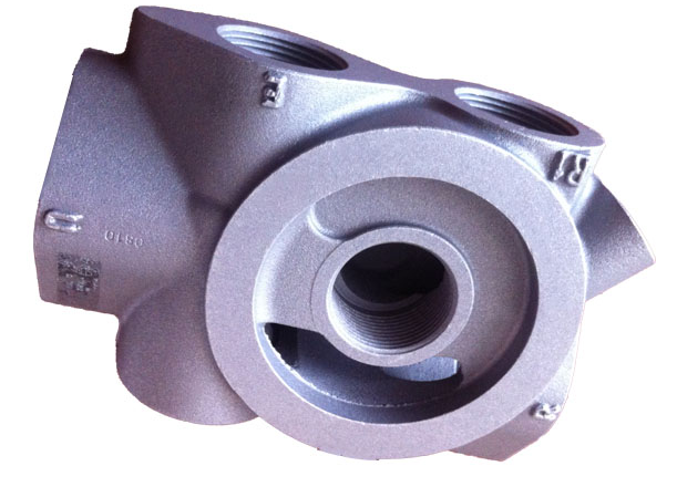
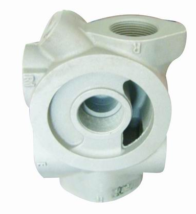
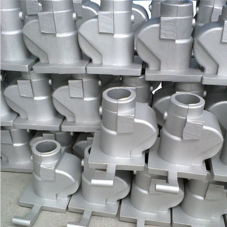
For an ISO 4401 hydraulic valve mounting-surface RFQ, name the exact interface code and controlling drawing or standard edition; identify whether Bohua supplies the valve body, subplate, manifold block or another cast-and-machined component; map every port, fixing hole and locating feature; and define the final mounting face, datum system, CNC state, cleanliness, protection, inspection records and assembly-test owner. Saying only CETOP or ISO valve face is not enough to approve interchangeability, sealing or system performance.
ISO 4401 addresses mounting surfaces for four-port hydraulic directional control valves so the interface can be defined consistently. The buyer still has to identify the valve model, interface size and code, optional pilot or drain ports, fastener system, mating component, material, final machining state and project acceptance evidence. The component supplier should manufacture and inspect the controlled interface; it should not infer a hydraulic circuit or guarantee an assembled system from a generic standard reference.
Bohua's current site verifies aluminum valve-body categories, A356 or ZL114 casting, casting plus CNC machining, ports, bores, threads, sealing and mounting faces, drawing review, fixture planning and dimensional inspection resources. Those pages and approved images establish category and workflow relevance only. They do not prove that a pictured part conforms to a named ISO 4401 interface or that a new assembly has passed pressure, leakage, flow or interchangeability validation.
Lock the valve and interface identity before quotation
Start with the valve manufacturer, model, function and controlled data sheet. State the full ISO 4401 mounting-surface code or buyer-controlled interface drawing, its edition or revision, nominal interface size, port arrangement and any optional pilot, drain or tank connection. If the interface is only described by a trade name such as CETOP or NG, add the exact dimensional source that governs the RFQ.
Define what Bohua is being asked to deliver: a cast valve body, a subplate, a manifold block with a machined valve pad, a cover or another interface component. Also state who supplies the mating valve, seals, screws, locating pins and any intermediate plate. A quote cannot be compared when one supplier prices a finished interface and another prices only a rough casting.
Separate the standard interface from the project drawing
DIN Media lists ISO 4401:2005 as current and describes it as the mounting-surface standard for four-port hydraulic directional control valves. Use the standard to identify the applicable interface, then place the selected code, project-specific details and drawing revision in the controlled RFQ package. Do not copy dimensions from a similar valve or rely on an old catalog label.
The buyer drawing should resolve every project option not fixed by the selected interface: component envelope, casting stock, mounting-pad boundary, optional ports, port depth, passage connection, fastener depth, locating features, coating or masking, seal ownership and inspection notes. The standard reference does not replace the valve manufacturer's current data sheet or the buyer's assembly drawing. Source: https://www.dinmedia.de/en/standard/iso-4401/83886002 .
Map ports, fixing holes and locating features
Create one interface schedule that uses the same identifiers as the valve data sheet and hydraulic schematic. Map pressure, tank and work ports plus any pilot, drain or optional tank port; identify fixing holes, thread system, minimum full-thread requirement when specified by the controlling drawing; and show locating-pin holes or other orientation features. Mark unused or blocked connections explicitly.
The port schedule should connect the mounting face to the internal cast or drilled passages without asking the machining supplier to infer circuit function. It should also identify the acceptable rule when the ISO code, valve data sheet, 2D drawing and 3D model appear inconsistent. A dimensionally accurate mounting pad can still connect the wrong passages if the P, T, A and B map is ambiguous.
Define the mating component and sealing boundary
State whether each sealing ring is carried by the valve, subplate, manifold or intermediate plate. Identify the approved seal part number or controlling seal drawing, permitted material choices, recess ownership, installation owner and protection state. Define whether the RFQ covers only the empty machined component, a valve mounted for fit-up, or a tested assembly.
ARGO-HYTOS installation guidance for one ISO 4401 valve family requires a clean, undamaged mating surface, correct port alignment and intact sealing rings before mounting. This is useful evidence that assembly condition matters, but it is product-specific guidance rather than proof of Bohua's process or a universal torque, seal or test rule. Source: https://www.argo-hytos.com/fileadmin/user_upload/RPE4-10_manual_EN_14039.pdf .
Put mounting-face geometry and final state on the drawing
Identify the exact mounting-pad boundary, controlling datum frame and relationship to ports, bolt holes, locating holes, adjacent bores, external ports and assembly faces. State flatness, surface texture, allowed waviness and damage, edge condition, cleanliness and whether acceptance applies after final machining, coating, washing and protection. If the buyer has not finalized a numerical requirement, require the supplier to list its proposed value and inspection method as a quote assumption.
Danfoss technical information for ISO 4401 interfaces distinguishes a machined mounting pad and gives product-family requirements for flatness, smoothness, threads and interface drawings. Use the selected valve documentation rather than transferring one product's numbers to every interface. Source: https://assets.danfoss.com/documents/latest/248893/BC449980331887en-000101.pdf .
Connect casting stock, heat treatment and CNC sequence
Treat the ISO mounting face as a finished machined interface supported by a casting plan. Show local stock, wall transitions, cored or drilled passage relationships, fixture access, datum candidates, alloy and heat-treatment state and the sequence that creates the final face, ports and threads. Identify whether rough machining occurs before heat treatment and which condition controls final acceptance.
Bohua's current valve-body and casting-plus-CNC pages verify A356 or ZL114 categories, gravity casting, downstream machining of ports, bores, threads, sealing or mounting surfaces, drawing review, fixture planning and dimensional verification. The exact casting route, stock, tool, fixture and heat-treatment sequence for a new interface must still be reviewed against its controlled drawing. General capability pages do not establish cleanup, tolerance, pressure rating or functional performance for a new part.
Control passage intersections, burrs and delivered cleanliness
Mark where mounting-face ports connect to cast or drilled passages and where hidden intersections can retain chips or burrs. Define protected metering and sealing edges, acceptable edge breaks, inspection access, chip-removal and washing method, dryness, closure or capping, corrosion protection and receiving condition. Do not use cleanliness as an undefined one-word requirement.
Separate visual surface acceptance from internal passage evidence. If the buyer requires borescope inspection, flushing, gravimetric analysis, particle counting or another method, state the method, acceptance value, sample frequency and record format. Bohua's public pages do not verify one universal cleaning method or contamination code, so those controls must be quoted and approved per project.
Build component, fit-up and functional evidence layers
Use separate evidence columns. Component evidence can cover mounting-face flatness and texture, port and hole position, pin-hole size, thread results, passage connection, burr condition, cleanliness and material or heat-treatment records. Fit-up evidence can cover valve orientation, port alignment, seal and fastener identity and non-destructive assembly checks. Functional evidence can cover external leakage, internal leakage, pressure, flow or system behavior only when the buyer defines the test method and acceptance.
Bohua's quality page verifies CMM support for dimensions, geometric tolerances, hole position, profile and flatness. The RFQ still needs the datum frame, support or fixture state, inspection method, report format and frequency for each characteristic. A CMM report on an empty mounting surface does not prove valve interchangeability, sealing, pressure capacity or hydraulic-system function.
Control first-article, production and change records
For first articles, identify the ballooned drawing, dimensional report, mounting-face form and texture result, port and hole position, thread and pin-hole records, burr and cleanliness evidence, material and heat-treatment records, valve data sheet and fit-up or functional evidence when included. For production, define controlled characteristics, sampling or all-part checks, gauge identification, calibration status, traceability, retention period and reaction plan.
Require approval for changes to the valve model, ISO interface code or edition, buyer drawing, material or heat treatment, casting route, tooling, CNC program, fixture, inspection method, deburr or cleaning process, coating or masking, seal or fastener source, subcontractor and repair route. A nominally compatible interface change can alter machining, inspection and assembly risk.
Normalize the quote and submit a drawing-ready RFQ
Ask every supplier to separate casting tooling, raw casting, heat treatment, rough and finish machining, interface tools, fixtures, gauges, CMM or surface records, first-article documents, deburr and cleaning, seals and fasteners, valve fit-up, leak or functional tests, protection, packaging and export terms. Confirm whether the quote covers one mounting pad, multiple valve stations or a complete manifold and whether the mating valve is buyer-supplied.
Current Bohua evidence and buyer routes: https://www.bohua-casting.com/applications/valve-body ; https://www.bohua-casting.com/valve-body-manufacturer ; https://www.bohua-casting.com/products/screw-machine-vacuum-pump-hydraulic-valve-32 ; https://www.bohua-casting.com/products/screw-machine-vacuum-pump-hydraulic-valve-33 ; https://www.bohua-casting.com/products/screw-machine-valve-body-38 ; https://www.bohua-casting.com/aluminum-casting-cnc-machining-supplier ; https://www.bohua-casting.com/materials/a356 ; https://www.bohua-casting.com/quality-control . Adjacent guides: https://www.bohua-casting.com/blog/valve-body-port-thread-inspection-records-rfq ; https://www.bohua-casting.com/en/resources/hydraulic-cartridge-valve-cavity-machining-rfq/ .
Send the controlled PDF and STEP files, valve model and data sheet, ISO interface code and edition, port and hole map, mating-component and seal boundary, alloy and heat-treatment target, final mounting-face requirements, inspection and cleanliness package, annual volume, tooling status, functional-test scope, destination and timing through https://www.bohua-casting.com/request-quote?source=jhclaw-content . Bohua can then review the defined cast-and-machined component without treating a standard name or product image as proof that the assembly is already validated.
Specifications
| Valve and interface identity | Valve manufacturer and model, function, full ISO 4401 interface code, edition or controlled interface drawing and nominal size |
|---|---|
| Supply boundary | Valve body, subplate, manifold block, cover or other component; raw, heat-treated or finish-machined state; owner of valve, seals, screws and pins |
| Governing files | Buyer PDF and STEP revisions, valve data sheet, ISO reference and conflict-resolution authority |
| Port map | P, T, A and B plus pilot, drain or optional ports, internal passage connections, blocked paths and schematic cross-reference |
| Fixing and location | Bolt-hole pattern, thread system and depth, locating-pin holes, orientation features, fastener source and assembly owner |
| Sealing boundary | Seal part or drawing, recess owner, mating surface, installation owner, permitted material and protected delivery state |
| Mounting face | Pad boundary, flatness, texture, waviness or damage rules, final machining or coating state and receiving cleanliness |
| Datum relationship | Datum frame and relationship among face, ports, holes, pins, adjacent bores, external ports and assembly references |
| Casting and CNC state | Alloy and temper target, casting-route review, stock, passage relationship, heat-treatment sequence, fixture and final acceptance stage |
| Burr and cleanliness | Intersection map, protected edges, burr criteria, wash and dry method, verification, capping, corrosion protection and packaging |
| Inspection and tests | Characteristic, datum and support state, CMM, form, texture, thread or dedicated gauge, report frequency, fit-up, leak and functional boundary |
| Records and changes | First-article and production records, traceability, gauge status, deviations, reaction plan, change approval, commercial exclusions and export terms |
FAQ
What should a buyer include in an ISO 4401 hydraulic valve mounting-surface RFQ?
Include the valve manufacturer and model, full ISO 4401 interface code and edition, controlled PDF and STEP files, port and hole map, mating component and seal boundary, material and final CNC state, mounting-face requirements, datum plan, cleanliness, inspection records, annual volume and assembly or test ownership.
Is CETOP or NG size alone enough to define the mounting surface?
No. Those names can help identify a family, but the RFQ should state the exact interface code or controlled drawing, valve data sheet, edition or revision, optional ports, fastener system and project-specific requirements.
Does ISO 4401 prove that a valve and cast manifold will seal and work together?
No. The standard helps define a mounting interface. Compatibility and performance also depend on the selected valve, seals, mating component, correct port mapping, manufacturing and inspection results, assembly condition and buyer-defined leak, pressure, flow or system tests.
What inspection evidence is useful for a valve mounting surface?
Useful evidence can include the mounting-face flatness and texture result, port and hole position, locating-hole and thread records, passage connection, burr and cleanliness checks and the drawing-linked datum setup. Fit-up and functional tests should be listed separately.
What should a buyer send Bohua for review?
Send PDF and STEP files, the valve model and data sheet, ISO interface code and edition, port and fixing map, alloy and heat-treatment target, final machining and surface requirements, inspection package, seal and fastener responsibility, annual demand, tooling status, test acceptance, destination and launch timing.