
Make industrial valve-body quotations comparable by separating installation length from each end-interface definition, final CNC evidence, assembled-test ownership, records and quote exclusions.
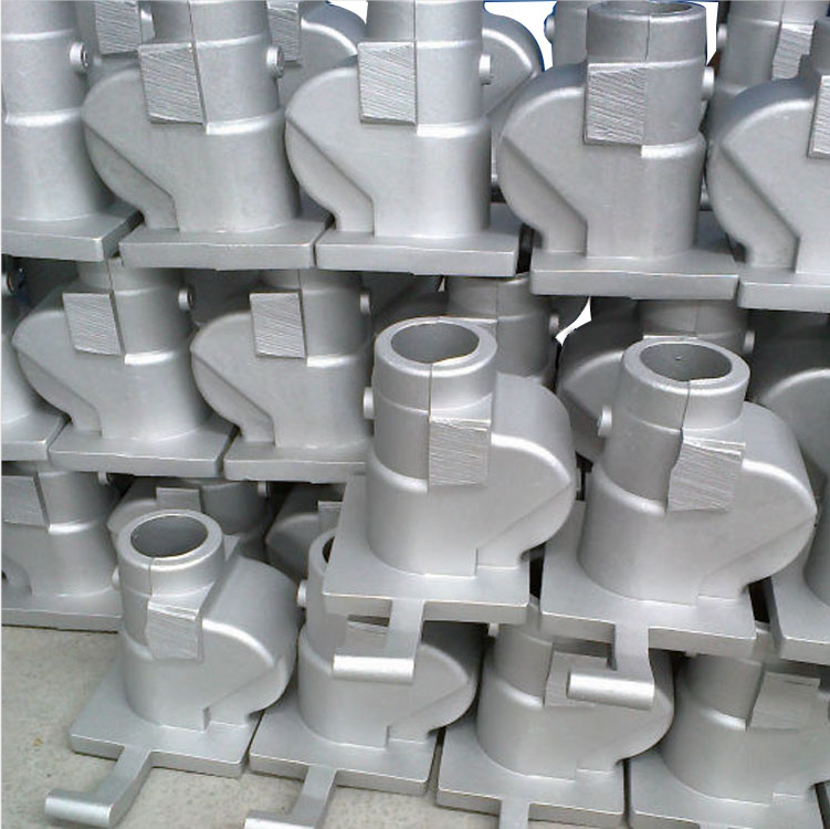
A quote-ready industrial valve body RFQ must separate three controls: the installed valve length, each inlet and outlet interface, and component-versus-assembled acceptance. State the exact valve and body identity, end style, governing drawing or standard and edition, face-to-face, end-to-end or center-to-end dimension, flange or other connection definition, final CNC state, inspection evidence, and who owns mating parts and complete-valve tests. NPS, DN, pressure class or a product photograph alone is not a complete body specification.
Face-to-face is the controlled distance between defined end faces for a straightway valve. Other body arrangements may use end-to-end, center-to-face or center-to-end control. The end interface is a separate definition that can include size, rating class or PN, facing, bore, bolt pattern, local geometry, finish and delivered protection. The buyer or valve designer must release the applicable dimension source, edition and conflict rule for the exact valve architecture.
Bohua's current site verifies one ZL114 or A356-family industrial valve-body casting example for compressor and equipment flow-control systems. Its product evidence names gravity casting, machining planning, bore position, sealing faces and inspection reporting. This proves product-family and workflow relevance only. It does not prove that Bohua owns a buyer's valve design, pressure class, standard dimensions, flange joint design, pressure rating, assembled leakage class or complete-valve validation.
Identify the valve, body and delivered supply state
Start with the valve family, service, flow direction, straightway or angle arrangement, body part number, nominal size or project identifier, controlled PDF and STEP revisions, material target and installed orientation. Name each end style, such as flanged, flangeless or another buyer-defined interface, without assuming that one valve standard covers every body feature.
Define the delivered state: raw casting, heat-treated blank, rough-machined body, finish-machined and cleaned body, body with temporary protection, partly assembled body or complete valve. List who supplies and installs mating flanges, gaskets, seals, bolting, trim, bonnet, packing and actuator. Also identify who owns body pressure testing, assembled external-leak testing, seat leakage, travel and complete-valve functional validation. A casting-only quote and a complete-valve quote are not comparable until this boundary is explicit.
Separate installation length from the end-interface definition
Treat the body length and the connection geometry as two linked but separate controls. The length schedule should identify the measurement type, its endpoints, nominal value and tolerance, governing source, installed or free state, coating or gasket assumptions and final inspection state. The connection schedule should identify every feature needed to mate the body to the buyer-controlled piping, subplate, manifold or adjoining component.
ASME's current B16.10 product page identifies face-to-face and end-to-end dimensions for straightway valves and center-to-face and center-to-end dimensions for angle valves, with installation interchangeability as the purpose. Use that scope to choose the correct measurement name and governing source; do not copy a value from an unrelated valve. Source: https://www.asme.org/codes-standards/find-codes-standards/b16-10-face-face-end-end-dimensions-valves/2017 .
Freeze the standard, drawing and edition hierarchy
List the buyer drawing, assembly drawing, purchase specification, valve standard, flange or connection standard and every applicable edition. State which source controls when a project drawing, selected standard table and mating-part model disagree. If the design is proprietary or partly standard-based, mark the standard-derived features and the drawing-controlled exceptions separately.
The ASME B16.5 product page currently lists the 2025 edition and describes coverage including pressure-temperature ratings, materials, dimensions, tolerances, marking, testing and opening designation for specified pipe flanges and flanged fittings. That does not make B16.5 a complete valve-body design rule. The RFQ must state whether and how its interface requirements apply to the exact cast body. Source: https://www.asme.org/codes-standards/find-codes-standards/b16-5-pipe-flanges-flanged-fittings-nps-1-2-nps-24-metric-inch-standard .
Build one schedule for every inlet and outlet interface
Give each end a feature ID and define its function, end style, size, class or PN when applicable, facing or sealing form, outside and inside geometry, bore transition, thickness, hub or local wall transition, bolt circle or through-bolt arrangement, hole size and orientation, surface condition, edge rule, coating mask, cleaning state and shipping protection. Tie every entry to the controlled drawing or standard edition.
Do not let an inlet and outlet share one generic note when their axes, facing, bore, clocking or machining state differ. If a flangeless body is clamped between mating flanges, identify the alignment, gasket, through-bolt and installed-length assumptions owned by the valve designer. If the interface is threaded, welded or project-specific, replace flange fields with the applicable buyer-controlled details rather than forcing the wrong standard language.
Define the face-to-face measurement state and datum plan
State which physical faces establish the dimension, whether the body is measured before or after final machining, whether coating is excluded or included, whether integral seals or separate gaskets affect the installed dimension, and whether the result is accepted in a free, supported or assembled state. Show the datum frame used for end-face spacing, parallelism, perpendicularity, bore or passage axis and connection orientation.
A current Emerson product bulletin provides a useful architecture example by listing flangeless end-connection compatibility separately from compact face-to-face dimensions. The lesson is the separation of mating-interface compatibility and installed length, not the adoption of that product's dimensions for a Bohua RFQ. Source: https://www.emerson.com/is/content/emerson/en/final-control/flow-controls/documents/d104550x012.pdf .
Connect casting stock, heat treatment and final CNC
Map the casting walls and transitions around each end, the internal flow path, local bosses, cored or drilled features, parting and feeding-sensitive zones, machining stock, heat-treatment state, rough cuts, finish cuts, fixture supports, datum transfers, deburr, cleaning and final protection. Identify which datum exists in each manufacturing state and which end faces or bores must be created in one setup or re-established by inspection.
Bohua's live valve-body example identifies ZL114 or A356-family gravity casting, machining datum planning, sealing-face relevance and inspection reporting. Bohua's casting-plus-CNC, ZL114 and quality pages support drawing-based review. The exact stock, fixture, process sequence, feasible tolerance, heat-treatment route, inspection frequency and repair authority for a new body remain project-specific and must be confirmed from controlled files.
Choose inspection evidence by feature and manufacturing state
Build an inspection matrix that names each controlled characteristic, its source, final state, support condition, datum, method, instrument or gauge, first-article scope, production frequency, record format, traceability and reaction after failure. Possible evidence includes final face spacing, connection-axis relationship, facing and bore results, bolt-hole position or clocking, surface checks, CMM or dedicated-gauge output and an assembly fit-up result when the mating definition is available.
Separate direct measurements from derived or assembled results. A CMM report on an unsupported body may not represent an installed dimension if the acceptance definition requires a clamped assembly. A flange gauge or mating master may check fit but not prove body pressure integrity. The buyer should release the feature-by-feature acceptance method instead of requesting one generic dimensional report.
Separate body, joint and complete-valve acceptance
Use separate evidence layers. Layer one covers material and casting condition. Layer two covers final body dimensions and end interfaces. Layer three covers a bare-body or component pressure boundary under a defined fixture and plugged-port map. Layer four covers the assembled external joint with the approved mating parts, gaskets, bolting and assembly procedure. Layer five covers seat leakage, actuator travel and complete-valve functional performance when required.
Passing one layer does not prove the others. Final face-to-face inspection does not prove a flange joint will seal. A body pressure test does not prove seat shutoff or actuator performance. For each required test, state the owner, assembly state, medium, pressure or operating condition, stabilization, acceptance source, frequency, record and authority for retest, repair or disposition.
Control records, changes, deviations and delivered protection
Require approval for changes to the body or mating revision, standard edition, end style, class or PN, facing, installed-length definition, alloy or heat-treatment route, casting process, tooling, cores, repair method, machining stock, CNC program, fixture, datum, gauge, inspection method, coating mask, cleaning, packaging and subcontractor. A mating-flange or gasket change can alter the assembly boundary even when the body part number appears unchanged.
Define how nonconforming end faces, bores, bolt patterns, local walls or pressure-boundary features are identified and prevented from silent rework. State whether weld repair, impregnation, thread repair, metal removal, re-machining or use-as-is disposition is prohibited, conditionally allowed or subject to buyer approval, followed by the required dimensional and test evidence. Protect final faces and openings against impact, chips, moisture and contamination during delivery.
Normalize the quotation and send a drawing-ready RFQ
Ask every supplier to separate tooling, cores, raw casting, heat treatment, rough and finish CNC, fixtures, gauges, dimensional reports, project-defined internal inspection, cleaning, temporary protection, bare-body tests, mating hardware, assembly, joint tests, complete-valve tests, packaging and export terms. Record every exclusion and open assumption next to the relevant interface, not in a general note after pricing.
Current Bohua evidence and buyer routes: https://www.bohua-casting.com/products/screw-machine-valve-body-38 ; https://www.bohua-casting.com/applications/valve-body ; https://www.bohua-casting.com/valve-body-manufacturer ; https://www.bohua-casting.com/aluminum-casting-cnc-machining-supplier ; https://www.bohua-casting.com/quality-control ; https://www.bohua-casting.com/materials/zl114 . Adjacent guidance for trim alignment remains at https://www.bohua-casting.com/en/resources/industrial-valve-body-seat-pocket-stem-alignment-rfq/ .
Send the controlled body and assembly PDF and STEP files, end-interface schedule, installed-length definition, material and process target, final CNC and inspection plan, pressure and assembled-test responsibilities, annual volume, tooling status, destination and timing through https://www.bohua-casting.com/request-quote?source=jhclaw-content . Bohua can then review the defined cast-and-machined body without treating a standard name or product image as complete design authority.
Specifications
| Valve and body identity | Valve family, service, flow direction, straightway or angle arrangement, body part number, size or project ID, orientation, PDF and STEP revisions |
|---|---|
| Delivered supply state | Raw, heat-treated, rough-machined, finish-machined, protected, partly assembled or complete; owner of mating parts, assembly and tests |
| Governing source | Buyer drawing, assembly drawing, purchase specification, valve and connection standards, editions, exceptions and conflict rule |
| Installation length | Face-to-face, end-to-end, center-to-face or center-to-end name, endpoints, value, tolerance, state and source |
| End-interface identity | Feature ID, inlet or outlet function, end style, size, class or PN, facing or sealing form, and mating component revision |
| End geometry | Face, bore, transition, thickness, local wall, bolt circle or through-bolt arrangement, hole size, orientation and edge rule |
| Material and casting state | Alloy and condition, gravity-casting review, wall and flow-path map, stock, heat treatment, traceability, repair and deviation authority |
| CNC and datum plan | Rough and finish stages, fixtures, supports, datum transfers, faces or bores made together, deburr, cleaning and final state |
| Dimensional evidence | Feature, datum, support state, CMM or gauge method, first-article scope, production frequency, record and reaction plan |
| Joint ownership | Mating flange or component, gasket or seal, bolting, assembly procedure, coating mask, fit-up and external-joint acceptance owner |
| Pressure and functional evidence | Separate body-boundary, assembled-joint, seat-leakage and complete-valve tests with method, condition, acceptance, frequency and record |
| Commercial and change scope | Tooling, fixtures, gauges, tests, hardware and assembly inclusions, open assumptions, annual volume, destination, protection and change approval |
FAQ
What should a buyer include in an industrial valve body end-connection RFQ?
Include the exact body and assembly revisions, end style for every inlet and outlet, governing standard and edition, installed-length definition, interface geometry, final CNC and datum plan, inspection evidence, pressure and assembled-test ownership, annual volume and quote exclusions.
Is valve face-to-face the same as the flange specification?
No. Face-to-face or another installed-length definition controls the distance between specified endpoints. The flange or end-interface definition separately controls the mating geometry. The RFQ must state both sources and how conflicts are resolved.
Can a supplier select ASME B16.5 from NPS and pressure class alone?
Not safely. The buyer must identify the applicable standard and edition, material and rating basis, facing, mating component, bore and project exceptions. B16.5 does not replace the controlled valve-body and assembly drawings.
Does a body CMM report prove the assembled valve connection will seal?
No. CMM or gauges can verify defined body geometry in a stated support condition. Joint sealing also depends on the mating interface, gasket or seal, bolting, assembly procedure and test boundary, which require separate ownership and evidence.
What should a buyer send Bohua for end-connection review?
Send controlled body and assembly PDF and STEP files, the inlet and outlet schedule, installed-length definition, material and process target, casting and CNC scope, datum and inspection plan, body and assembled-test requirements, annual demand, tooling status, destination and timing.