
Make valve-body quotations comparable by identifying the cartridge and cavity family, controlling drawing or standard, geometry, port intersections, thread and sealing surfaces, CNC state, inspection, cleaning, records, and assembled-test boundary.
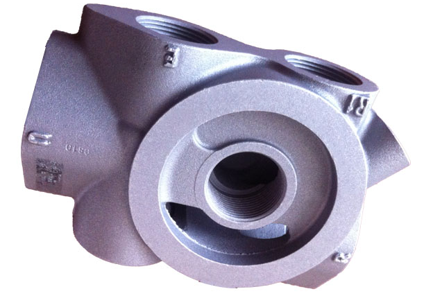
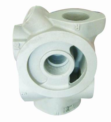
For a hydraulic cartridge valve cavity RFQ, identify whether the cavity is for a screw-in or slip-in cartridge; name the exact valve manufacturer, model, cavity code and controlling drawing or standard edition; map every cavity and cross-port to its function; and define cavity geometry, thread, sealing seat, finish, datum, final CNC state, deburr, cleanliness, inspection records and assembly or test responsibility. A valve-body model or cartridge name alone is not enough to approve compatibility, sealing or hydraulic-system performance.
The cavity is a machined interface between the supplied aluminum valve body and a separate functional cartridge. It can include multiple coaxial diameters, shoulders, angles, a thread or cover interface, seal regions and cross-port intersections. Component dimensions, cartridge installation, leak evidence and full system performance are separate acceptance layers and should be quoted separately.
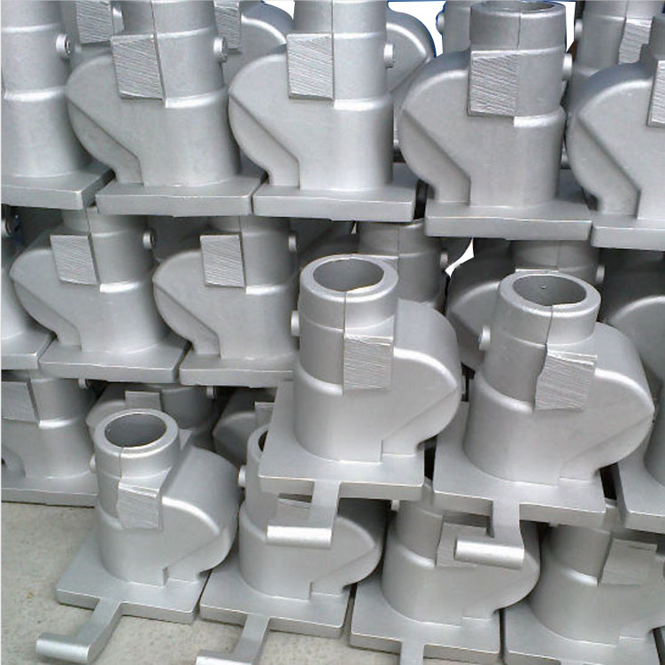
Bohua's current site verifies aluminum valve-body product categories, A356 or ZL114 casting, casting plus CNC machining, ports, bores, threads, sealing surfaces, drawing review and CMM resources. Those pages and approved images show category and workflow relevance only. They do not prove that a pictured part contains a named cartridge cavity, accepts a particular valve, has an approved project pressure requirement or has passed an assembled hydraulic test.
Lock the exact cartridge and cavity identity before quotation
Start with the functional cartridge, not a generic hole label. State the cartridge manufacturer, model or family, screw-in or slip-in type, number of working ports, cavity code, nominal size, drawing number, revision and the owner of the design. If a valve has not been selected, identify that as an open engineering decision rather than asking the supplier to infer a compatible cavity from the body model.
Define what Bohua is being asked to deliver: raw casting, heat-treated blank, fully machined valve body, valve body with a buyer-supplied cartridge installed, valve body with a supplier-sourced cartridge installed, or a tested subassembly. Also identify who supplies seals, plugs, covers, fasteners and installation tools. A quote that says only valve body with cartridge cavity does not establish a comparable scope.
Separate screw-in and slip-in control sources
Do not combine screw-in and slip-in cavities under one assumed geometry. A screw-in cartridge can depend on a particular thread, stepped diameters, shoulders and seal regions. A two-port slip-in cartridge uses a different cavity and cover or retention interface. The RFQ should name the exact controlling manufacturer drawing or the applicable standard and edition for the selected type.
DIN Media currently lists ISO 7368:2025 for two-port slip-in cartridge valve cavities and shows that it replaces the 2016 edition. Parker publishes cavity-specific valve and cavity compatibility pages with controlled drawings. These sources support edition and drawing control; they do not authorize Bohua to substitute a different cavity, select a cartridge, create a hydraulic circuit or approve a system pressure.
Map each cavity port to the hydraulic circuit
Provide a numbered port map that connects every cavity opening and cross-drilled passage to the hydraulic schematic. Identify pressure, tank, work, pilot or other project-defined functions; the cartridge port numbering; mating external ports; blocked or unused passages; and the flow direction or isolation logic that matters to inspection and testing.
The model, drawing and schematic should use the same port identifiers. If a manufacturer catalog uses a different numbering convention, add a cross-reference table. A dimensionally correct cavity can still be connected to the wrong passage if the port map is ambiguous. The cast-and-machined valve-body supplier should follow the controlled map, not infer circuit function from a photograph or product name.
Put the full cavity geometry on controlled files
The controlled PDF and STEP package should define the cavity axis, step diameters and depths, shoulder locations, angles, radii, chamfers, undercuts, thread, counterbore or cover interface, sealing lands, reliefs, lead-ins, local wall boundaries and cross-port locations. Identify which dimensions are basic, toleranced or reference-only and which drawing controls when 2D and 3D files disagree.
Do not copy dimensions from an unapproved similar cavity or rely on a tool name alone. If the buyer authorizes a manufacturer form tool, reamer, gauge or cavity standard, state the exact identifier and revision plus the dimensions and inspection results that still control the finished part. Proprietary dimensions should remain in the buyer's controlled drawing package rather than being recreated from a general article.
Connect casting stock, heat treatment and CNC sequence
Treat the finished cavity as a machined requirement that begins with the casting plan. Show local machining stock, wall transitions, core or drilled-passage relationships, datum candidates, alloy and heat-treatment state, reference surfaces and the sequence that creates the final cavity. Identify whether rough machining occurs before heat treatment and which state controls final dimensional acceptance.
Bohua's current valve-body and casting-plus-CNC pages verify A356 or ZL114 categories, gravity casting, downstream machining of ports, bores, threads, sealing surfaces and datums, drawing review and fixture planning. The exact casting route, stock, tool, program, fixture and heat-treatment sequence for a new cartridge cavity must still be reviewed against the new drawing. General pages do not establish cleanup, tolerance, density or functional performance for the new part.
Control cross-port burrs, chips and cleaning
Mark every place where a drilled passage intersects the cartridge cavity or another passage. Define which edges require a controlled break, which sealing or metering edges must not be rounded, how hidden burrs are inspected, how chips and abrasive residue are removed, and what receiving condition is acceptable. If flushing, borescope, visual, tactile, airflow or another method is required, state the method, access, acceptance and frequency rather than naming cleanliness in general.
Danfoss cartridge guidance tells users to follow the specific cartridge pages for port identification and inspect the cavity for burrs, chips or contamination before installation. That guidance supports an explicit cleanliness and deburr schedule. It does not prove that Bohua uses a particular cleaning process, borescope or contamination code on every valve body. Those controls must be quoted and approved for the project.
Define thread, seat, seal and installation ownership
For a screw-in cavity, define the thread form, size, pitch, class, engagement, start and gauge requirement plus the seal and backup-ring regions identified by the cartridge drawing. For a slip-in cavity, define the cartridge bore, cover or mounting interface, sealing regions, retention parts and any required orientation. For either type, state allowed surface damage, burr, chatter, corrosion, coating and handling conditions.
Separate cavity machining from cartridge supply and installation. State who verifies cartridge and seal identity, applies approved lubricant, controls installation torque or cover fasteners, protects the cavity before assembly and records the installed state. Do not assume a universal thread, surface finish, seal material, torque, adhesive or retention method. These values belong to the approved valve and cavity documentation.
Separate dimensional inspection from assembly evidence
Build separate evidence columns. Valve-body component evidence may include cavity diameters, depths, shoulders, axis position, thread gauge results, sealing surfaces, port locations, burr and cleanliness checks. Installed-component evidence may include cartridge and seal identity, installation record, torque or cover data and post-installation visual or dimensional checks. Assembled evidence may include leakage, pressure, flow, response or full circuit testing only when the buyer explicitly requires and defines it.
Bohua's quality page verifies CMM support for dimensions, geometric tolerances, hole position, profile and flatness. The RFQ must still name each characteristic, datum frame, support or fixture condition, gauge or CMM method, report format and frequency. A CMM report on the empty valve body does not prove cartridge compatibility, sealing, rated pressure, flow behavior or system function.
Control first-article, production and change records
For first articles, identify the required ballooned drawing, dimensional report, CMM or dedicated-gauge results, thread record, burr and cleanliness evidence, material and heat-treatment records, cartridge and seal identity, installation record and leak or functional evidence when included. For production, define controlled characteristics, sampling or all-part checks, gauge identification and calibration status, traceability, retention period and reaction plan.
Require buyer approval for changes to the valve or cavity family, manufacturer drawing, standard edition, material or heat treatment, casting route, tooling, CNC program, form tool or reamer, fixture, gauge, deburr or cleaning method, cartridge or seal source, installation method, repair or subcontractor. A technically similar change can alter the quoted risk and cannot be accepted through an undocumented supplier assumption.
Normalize the quote and route a drawing-ready RFQ
Ask every supplier to separate casting tooling, raw casting, heat treatment, rough and finish machining, cavity tools, CNC fixtures, gauges, CMM reports, first-article records, deburr and cleaning, cartridge and seal sourcing, installation, leak or functional tests, protection, packaging and export terms. Confirm whether the quote covers only the empty machined valve body or also the installed cartridge and assembled evidence.
Current Bohua evidence and internal routes: https://www.bohua-casting.com/applications/valve-body ; https://www.bohua-casting.com/valve-body-manufacturer ; https://www.bohua-casting.com/products/screw-machine-vacuum-pump-hydraulic-valve-32 ; https://www.bohua-casting.com/products/screw-machine-vacuum-pump-hydraulic-valve-33 ; https://www.bohua-casting.com/products/screw-machine-valve-body-38 ; https://www.bohua-casting.com/aluminum-casting-cnc-machining-supplier ; https://www.bohua-casting.com/materials/a356 ; https://www.bohua-casting.com/quality-control . Adjacent guides: https://www.bohua-casting.com/blog/valve-body-spool-bore-surface-finish-cleanliness-rfq-checklist ; https://www.bohua-casting.com/blog/valve-body-port-thread-inspection-records-rfq .
Send the controlled PDF and STEP files, valve manufacturer and model, cartridge type, cavity code and drawing revision, port map, alloy and heat-treatment target, cavity geometry, machining and cleaning scope, annual volume, tooling and gauge status, inspection records, installation boundary, leak or functional test scope, destination and timing through https://www.bohua-casting.com/request-quote?source=jhclaw-content . Bohua can then review the defined valve-body scope without treating product examples as proof that the new cavity or hydraulic system is already validated.
Specifications
| Cartridge and cavity identity | Manufacturer, valve model or family, screw-in or slip-in type, port count, cavity code, nominal size, drawing number and revision |
|---|---|
| Supply boundary | Raw casting, heat-treated blank, empty finished valve body, installed cartridge subassembly, or tested assembly plus owner of seals, plugs, covers and fasteners |
| Governing source | Controlled buyer drawing, approved manufacturer cavity drawing, named standard and edition, schematic and rule for resolving file conflicts |
| Port and circuit map | Cavity port numbers, pressure, tank, work or pilot functions, cross-passages, external ports, blocked paths and schematic cross-reference |
| Cavity geometry | Axis, step diameters and depths, shoulders, angles, radii, chamfers, undercuts, lead-ins, local wall boundary and cross-port locations |
| Thread and sealing interface | Thread form, size, pitch, class and gauge plus seat, seal lands, backup-ring regions, cover or retention interface and allowed surface condition |
| Datum relationship | Datum frame and cavity relationship to mounting face, adjacent bores, external ports, bolt pattern, sealing faces and other circuit features |
| Process state | Alloy and temper target, casting route review, machining stock, heat-treatment state, rough and finish CNC sequence, fixture and repair authority |
| Deburr and cleanliness | Cross-port intersection map, protected edges, burr acceptance, chip removal, flushing or cleaning method, inspection access and receiving condition |
| Inspection | Characteristic, datum and support state, CMM or dedicated gauge, thread gauge, visual or cleanliness check, report format and frequency |
| Assembly and test evidence | Empty-body dimensional report, cartridge and seal identity, installation record, torque or cover data, leak test and hydraulic-system test when explicitly scoped |
| Records and changes | First-article and production records, traceability, gauge status, deviations, reaction plan, change approval, commercial exclusions and export terms |
FAQ
What information should a buyer send for a hydraulic cartridge valve cavity RFQ?
Send the controlled PDF and STEP files, cartridge manufacturer and model, screw-in or slip-in type, cavity code and drawing revision, numbered port map, alloy and heat-treatment target, cavity geometry and finishes, datum plan, machining, deburr and cleaning scope, inspection records, annual volume and assembly or test boundary.
Is a screw-in cartridge cavity the same as a slip-in cartridge cavity?
No. They use different interfaces and control sources. The RFQ should identify the exact cartridge type and the approved manufacturer drawing or applicable standard edition rather than treating cartridge cavity as one universal geometry.
Can a supplier substitute a similar cavity or cartridge family?
Only with buyer engineering approval. A similar name or nominal size does not prove matching geometry, threads, seals, ports or function. Any substitution should be documented against the controlling valve, cavity and circuit requirements before tooling or production.
Does a CMM report prove that the cartridge will seal and function?
No. A CMM or gauge report can verify the empty valve-body cavity and its datum relationships. Sealing and function also depend on the correct cartridge and seals, installation state, port mapping and the buyer-defined leak, pressure, flow or system test.
What should a buyer send Bohua for review?
Send PDF and STEP files, the valve and cavity identification, circuit and port map, alloy and heat-treatment target, annual demand, tooling status, cavity machining and cleaning requirements, inspection package, cartridge supply and installation scope, test acceptance, destination and launch timing.